PROJECT DETAIL // GRAIN MILL RESURRECTION
1930s Technology. Digitized for Today.
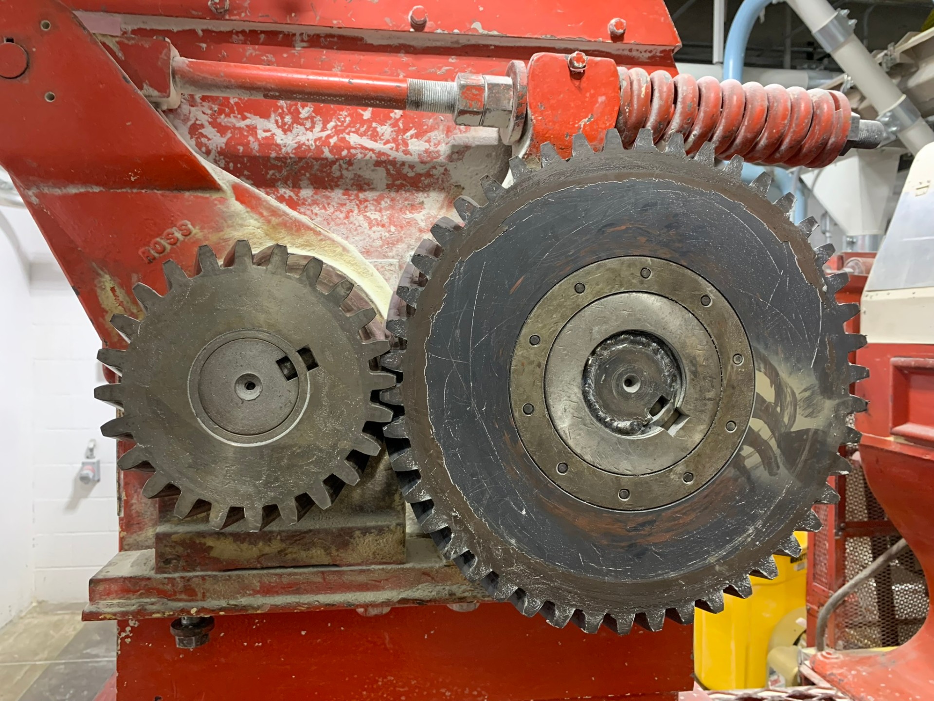
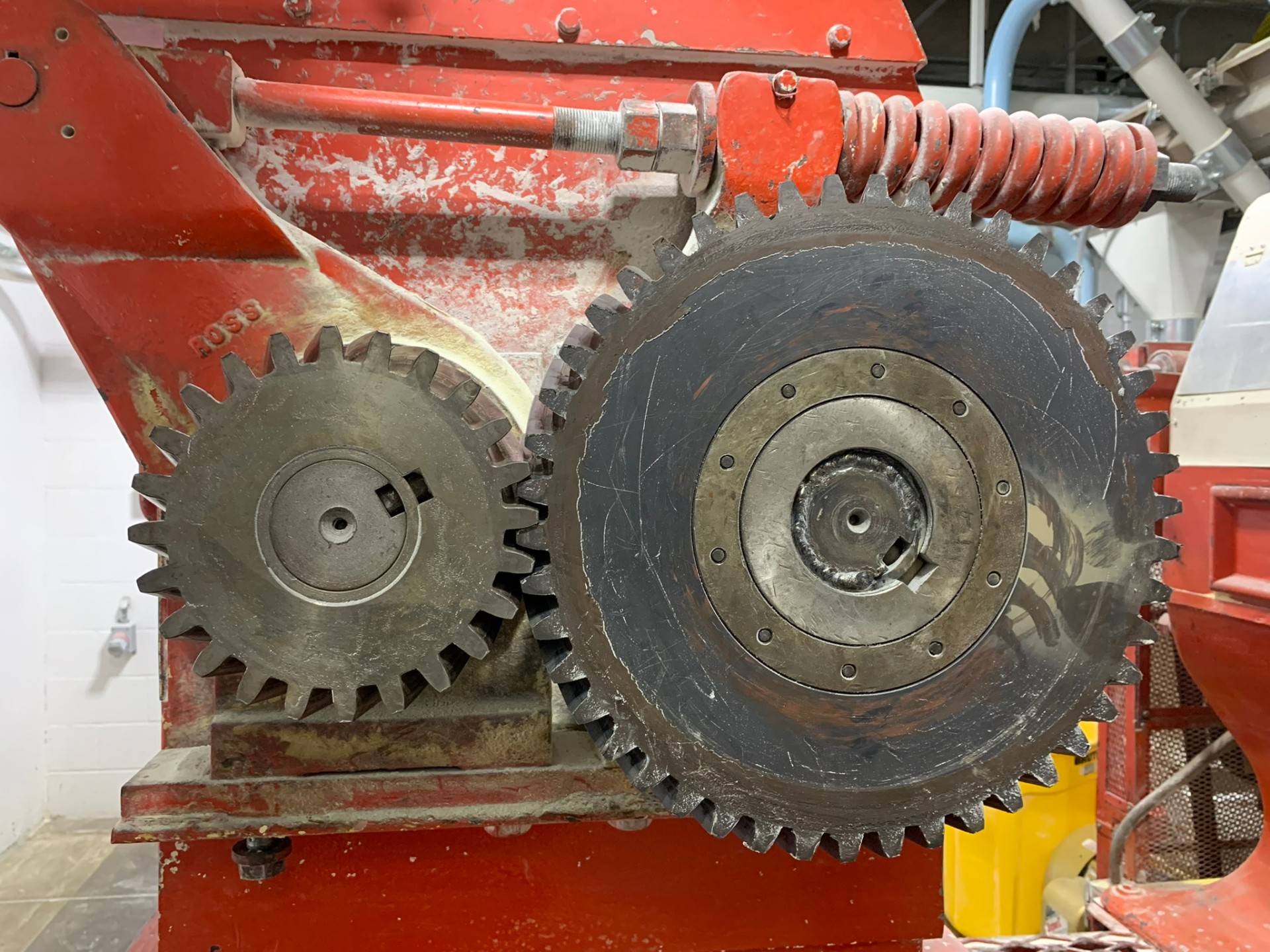
This grain mill gear (celebrating its 95th birthday!) is a testament to the leverage 3D scanning offers. The worn down teeth were digitally captured and restored to a nominal 3D solidworks model for CNC.
01 // THE CASE STUDY
Capture worn geometry and complex helical twist in a window of rare downtime.
This client project posed unique challenges. The machine ran lights out, 24/7, except once per month for maintenance and cleaning. Hand measuring in this tight window would be impossible. Thanks to 3D scanning, the entire geometry was saved, including the driving steel gear to double-check tooth alignment. A similar donor gear was provided separately to capture the standard mounting hole pattern and shape.
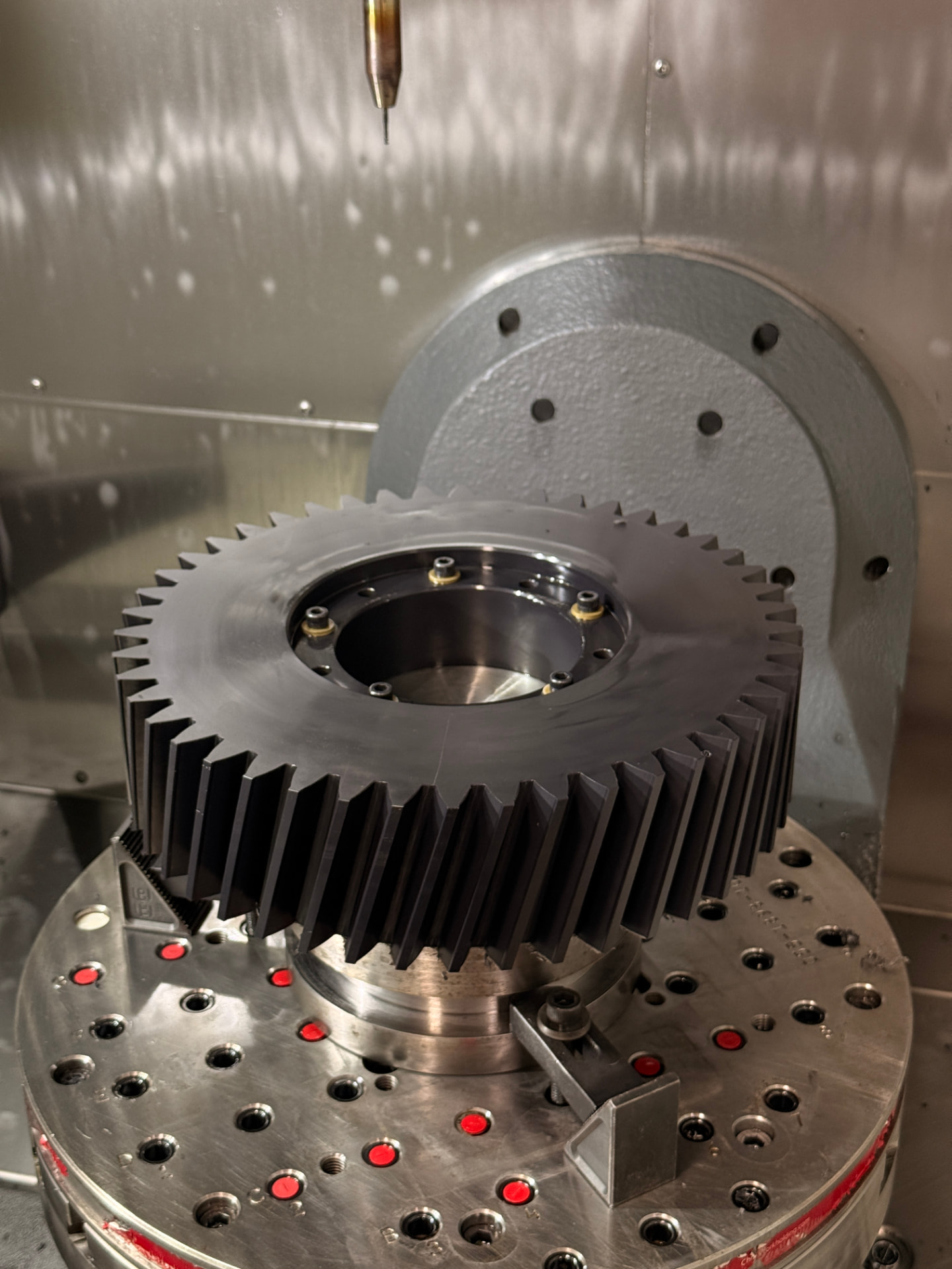
The project end goal was to provide a digital STEP CAD model, CAM program, and finally, a fully machined nylon-6 modern equivalent.
02 // CAD
Mesh validation before first chips.
By scanning both the driven nylon gear and the driving steel gear, the gear meshing is validated in CAD instead of post-machining.
03 // ADDITIVE
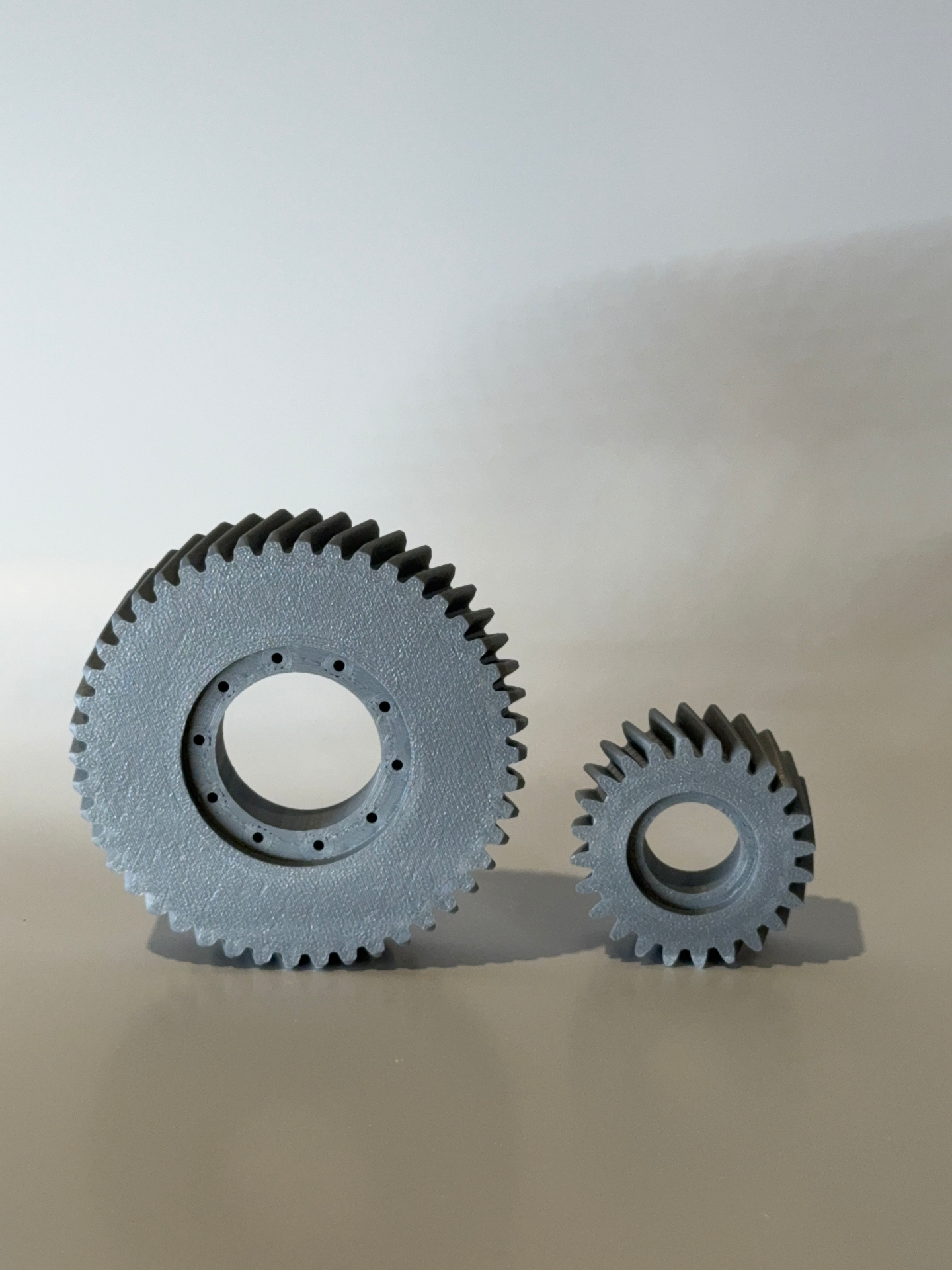
Scale mockups for demonstration.
While CAD models and simulations are desirable for validation, it is always helpful to physically hold the part to get a sense of function. It also helps to have a model to ensure CNC operations are as expected.
04 // PROJECT REVIEW
Engineering Obstacles. Key Takeaways.
- 01True parametric curve equations, not existing geometry, drove tooth shape. Allowed for proper meshing & decreased harmonics.
- 02In cases of running components, it is much easier to scan and work from a mesh than returning for missed measurements. Speeds up the process and ensures accuracy even when the scope changes.
- 03Building a CAD model allows for on-demand manufacturing with a cut-ready CNC program. Quickly modify the geometry, chamfers, fillets, for even more customization.
05 // FINISHED PART
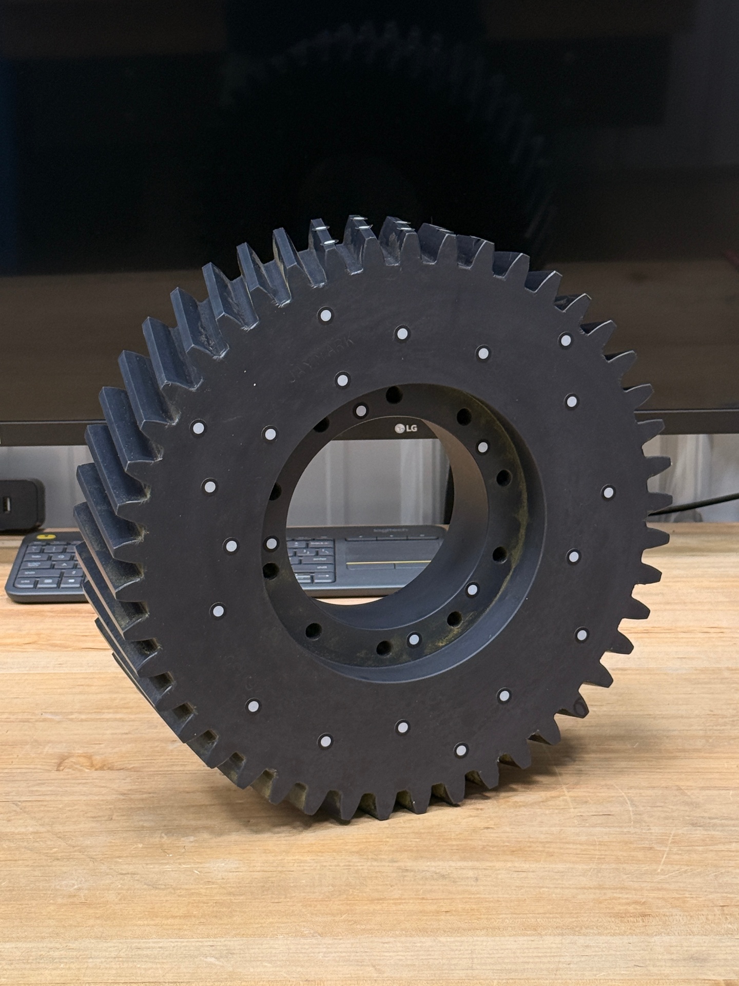
Machined for the next production cycle.
- 01Finished nylon-6 replacement gear
- 02CNC-machined tooth geometry
- 03Verified fit in the original assembly
05 // SPECIFICATION SHEET
06 · Engage
Have a legacy or NLA component?
Send us your details and we'll get back to you right away!